
|
|
Design and Analysis of Flows in Energy Systems |
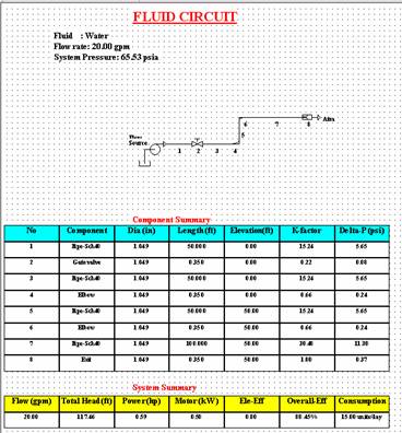 |
| The above circuit represents a water pipe line. The schematic follows symbols based on BS-1553. Graphical user interface is provided with in the model space where it will respond to all mouse clicks in order to edit, append and modify different components. The description space provides both component summary as well as system performance summary consists of total head, pump and motor ratings, overall efficiency and energy consumption data. |
| The above circuit is built initially using a single stream circuit builder. Components are added in exact sequence from the source to the exit or to the loading point. This circuit is then transormed and drawn in to the model space along with its descriptions. A seperate circuit builder is used for creating a pipe network involving several branches branching out from the main flow. The schematic for the branched flow is very much similar except that it will show the main branch with pressure and flow at each branching node. |