Energy Conversion
T
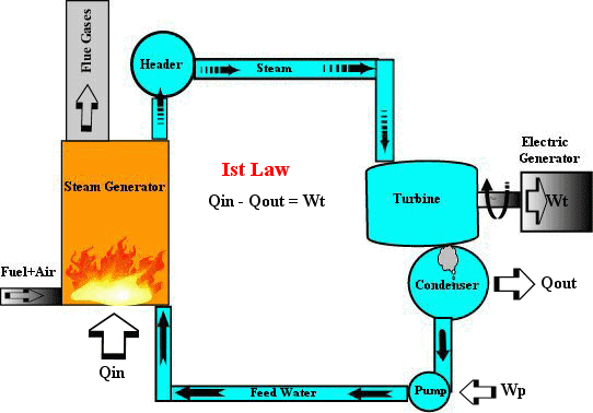
he energy conversion devices can be brought under two broad categories.- Devices that generate power (Heat engines, nuclear, water turbines, etc.)
- Devices that utilize power (Electric motors, hydraulic, pneumatic, etc.)

E
very heat engine has a source or a reservoir where heat is added to the fluid medium at an elevated temperature 'Th' and a sink where heat is rejected at a lower temperature 'Tl'. These two temperatures are the key parameters to know the upper bound on the amount of work a heat engine can produce and also known as its Carnot cycle efficiency. The second law dictates that no heat engine or device can produce work more than its Carnot efficiency and the actual thermal efficiency would lie somewhere below this line. Moreover, the overall efficiency is further reduced since its own auxiliaries such as pumps, fans etc., utilize a small part of the power so generated to keep the fluid medium under circulation.
E
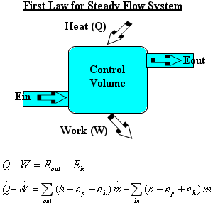
nergy conversion devices such as boilers, turbines, turbo engines, pumps and compressors can be treated as steady flow devices that have one or more fluid streams entering and leaving a control volume. The most important presumption is their stream properties at the inlet or outlet always remain the same regardless of the time. This concept is presented in the following model along with the energy balance equation and applicable to all flow systems analyzed in this program.
FJS
(Flow Joule System) Design analysis models are listed below. Flow Joule provides a generic model in each case that can be expanded and customized for any given situation in order to suit an individual application. Click on the models to find out how it can adapt to your situation.Besides, Flow Joule can also be a reference guide for the following.
- Steam Tables
- Properties of Gases and Liquids
- Pyschrometic Chart (Humid Air Properties)